We have seen the basic rules to design sheet metal components. Now we will see how a sheet metal flat pattern is calculated. First, we need to explain what the neutral axis is when a beam or a sheet metal is bended.
What is the neutral axis?
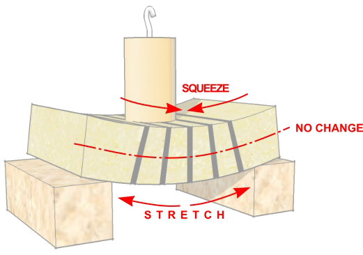
When a force is applied on top of a beam supported on 2 points, the beam is squeezed on the top surface and stretched on the bottom. In the middle way, there is a zone which is not squeezed or stretched. That zone is the neutral axis, and this neutral axis also exists when we bend sheet metal.
But where is positioned that neutral axis exactly?
The K-factor.
Before we explain where the neutral axis is, we must talk about the K-factor.
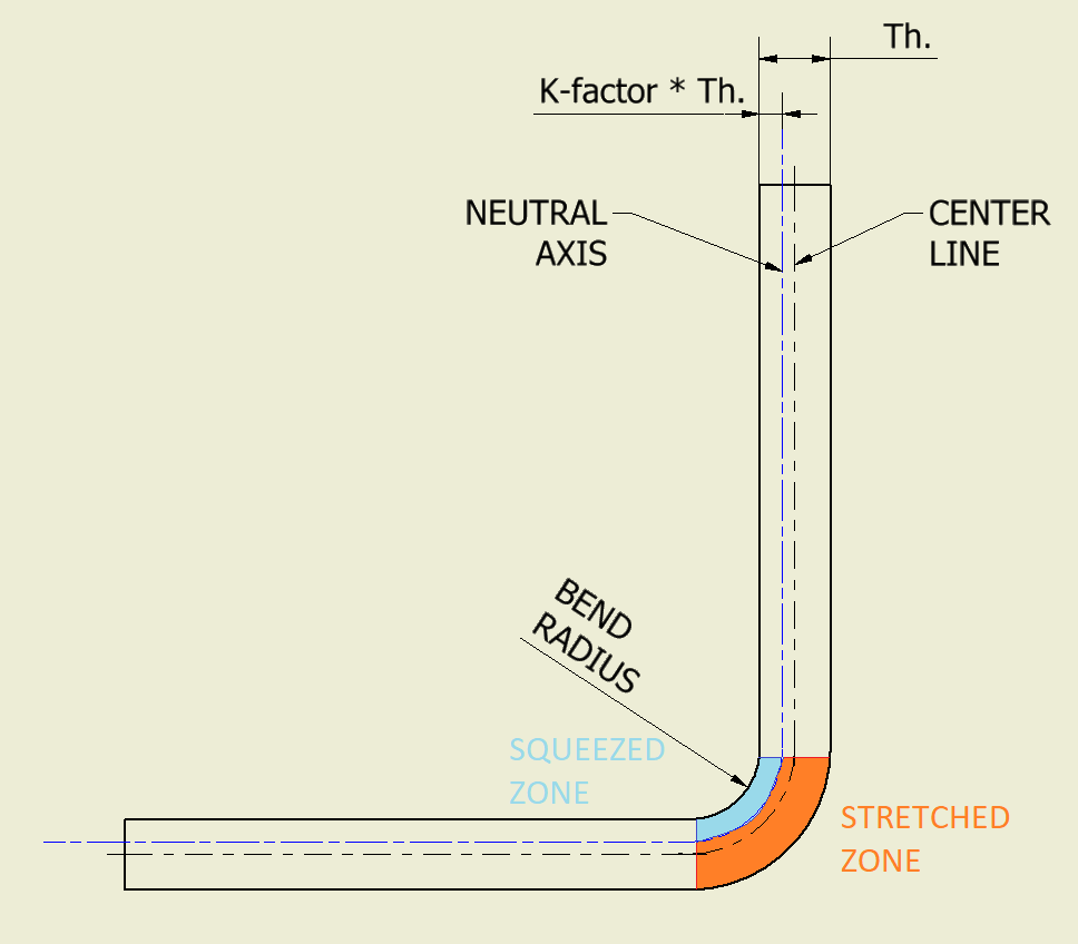
The K-factor indicates the relative position of the neutral axis in proportion to the sheet thickness. To understand the concept:
- A K-factor equal to 0 means the neutral axis is on top of the squeeze surface (where the bending force is applied)
- A K-factor equal to 1 means the neutral axis is on bottom of the stretched surface (opposite where the bending force is applied).
- A K-factor equal to 0,5 means the neutral axis is colinear to the centre line.
K-factor values for sheet metal
Unfortunately, sheet metal characteristics are not constant, and they may vary on each sheet. Its characteristics depend on the production process and even when the production process is the same, there isn’t any warrantee the characteristics are the same too. The K-factor also depends on the bending method and the bend radius.
Fortunately, it is possible to approximate the K-factor and get a good flat pattern later even with this issue. For steel and stainless-steel we have the following values when air-bending (the most common bending process):
| Bend radius | up to 1,5 times Thickness | from 1,5 up to 2,4 times Thickness | from 2,4 up to 3,8 times Thickness | over 3,8 times Thickness |
| K-factor (approx.) | 0,35 | 0,4 | 0,45 | 0,5 |
For other softer materials than steel like aluminium or polycarbonate, the K-factor has a smaller deviation from 0,5 when a small bend radius is applied.
How to calculate a sheet metal flat pattern
After talking about the neutral axis inside a bend, we can calculate the flat pattern.
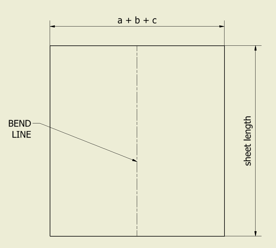
A sheet metal bend like the image on the right, has a flat patter equal to:
Flat pattern = a + b + c
Normally, sheet metal is quoted with the dimensions A and B, but we need the dimensions “a” and “b” in order to obtain the flat pattern length. We know the Thickness (Th.) of the sheet and the bend radius (Rb) which almost always is equal to the sheet thickness, so:
a = A – Th. – Rb = A – 2*Th.
b = B – Th. – Rb = B – 2*Th.
Now, the “c” length is quite tricky to calculate. This quote is the length of an arc with radius R and angle β, so.
c = 2 * R * π * β/360
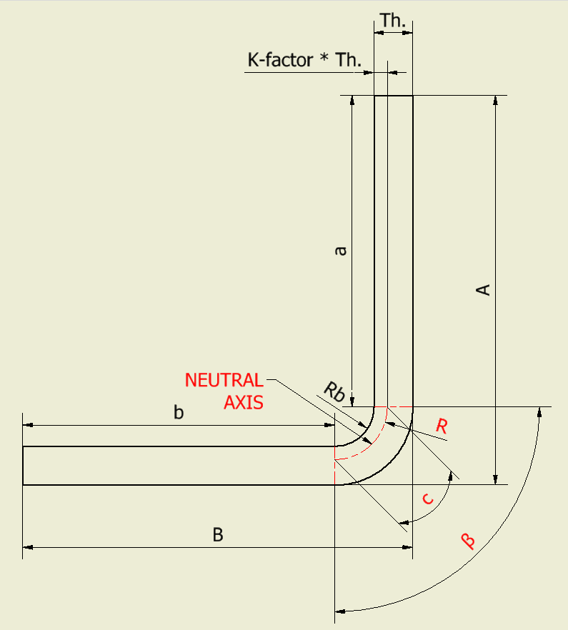
We can write R in function of bend radius (Rb) and we also know that bend radius (Rb) is almost always equal to the sheet thickness, so:
R = Rb + K-factor * Th. = Th. + K-factor * Th.
Now it is possible to re-write the “c” length as follow:
c = 2 * (Th. + K-factor * Th.) * π * β/360 = 2 * Th. * (1 + K-factor) * π * β/360
So, the flat pattern is calculated as follow if we assume bend radius (Rb) is equal to the sheet thickness:
| flat pattern | = | A – 2*Th. | + | B – 2*Th. | + | 2 * Th. * (1 + K-factor) * π * β/360 |
| flat pattern | = | a | + | b | + | c |
Otherwise:
| flat pattern | = | A – Th. – Rb. | + | B – Th. – Rb | + | 2 * (Rb + K-factor * Th.) * π * β/360 |
| flat pattern | = | a | + | b | + | c |
Notes and precision of this method
This is not the only method to obtain the sheet metal flat pattern of a component, but it is the most used on CAD systems.
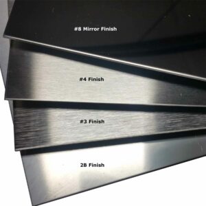
The precision depends on the regularity and constancy of the material properties (isotropy), the surface finishing (like coatings or shapes), the industrial process to obtain the sheet metal, and even on the tools used to work with it. Sometimes the workshop also uses different bend radius than designed (normally a smaller one).
Sheets are not constant in thickness, normally tends to be thicker than thinner. This lack of constancy added to the industrial process to obtain the sheet, makes it more rigid to bend in one direction than in other.
All these variations may also affect on the final sheet metal dimension and the reliability of the flat pattern. For this reason, it’s important to choose a good workshop (or to train your own workshop) when you need a precise sheet metal component.
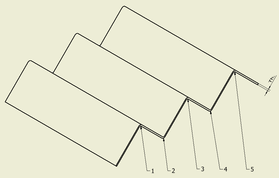
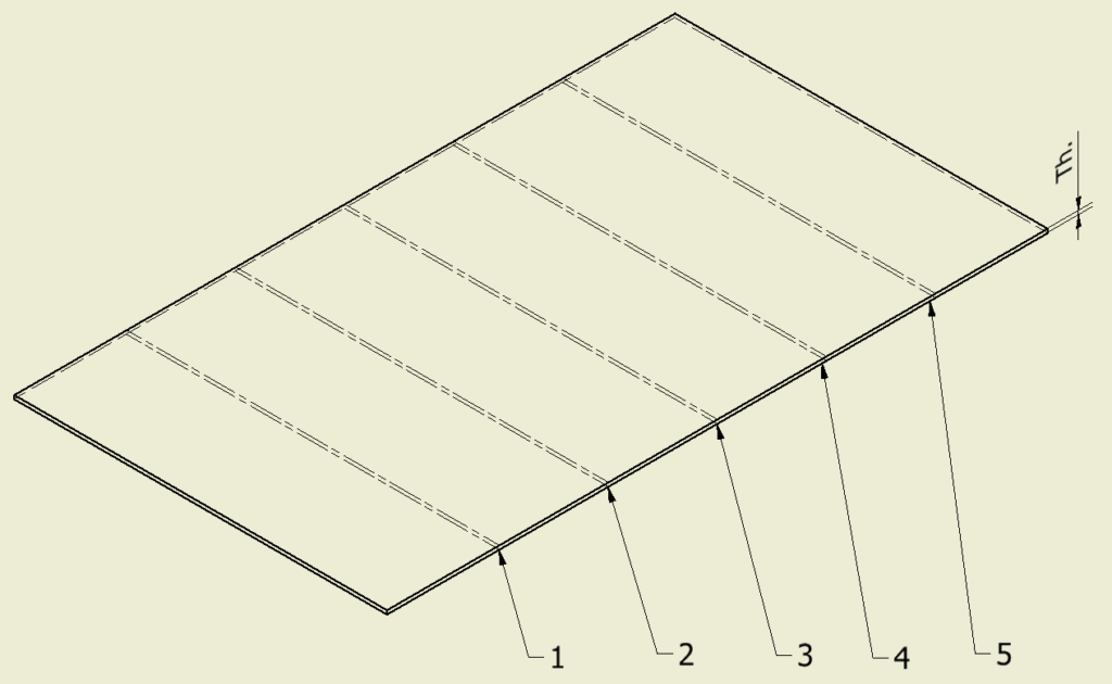
With the K-factor indicated above, the result will be precise enough for most cases up to following 5 bends. Over 5 following bends, it is recommended to indicate which bend is not dimensional relevant. In this case, the workshop can make all the bends with a precise dimension and any error on the flat pattern (maybe too long or short) is forced on that not dimensionally important bend.
Sheet metal is normally supplied in three width measures:
1000mm, 1250mm, and 1500mm.
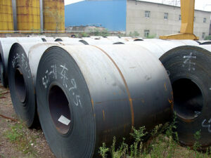
Sheet metal can be supplied in form of sheets or coils. The first may have a length between 2 and 6 meter long. The latter are cheaper and easier to handle but they need a straighten process before use it.